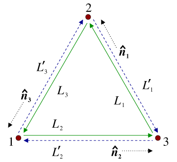
Figure 3: Schematic LISA configuration. The spacecraft are labeled 1, 2, and 3. The optical paths
are denoted by  ,
,  where the index
  corresponds to the opposite spacecraft. The unit
vectors
corresponds to the opposite spacecraft. The unit
vectors  point between pairs of spacecraft, with the orientation indicated.
, where the index corresponds to the opposite spacecraft. The unit
vectors point between pairs of spacecraft, with the orientation indicated.Massimo Tinto and Sanjeev V. Dhurandhar, "Time-Delay Interferometry",
Living Rev. Relativity, 17 (2014), 6, doi:10.12942/lrr-2014-6, URL (accessed <date>): http://www.livingreviews.org/lrr-2014-6. This work is licensed under a Creative Commons License.
© The author(s), except where otherwise noted.
This work is licensed under a Creative Commons License.
© The author(s), except where otherwise noted.
Living Rev. Relativity, 17 (2014), 6, doi:10.12942/lrr-2014-6, URL (accessed <date>): http://www.livingreviews.org/lrr-2014-6.
This work is licensed under a Creative Commons License.
© The author(s), except where otherwise noted.