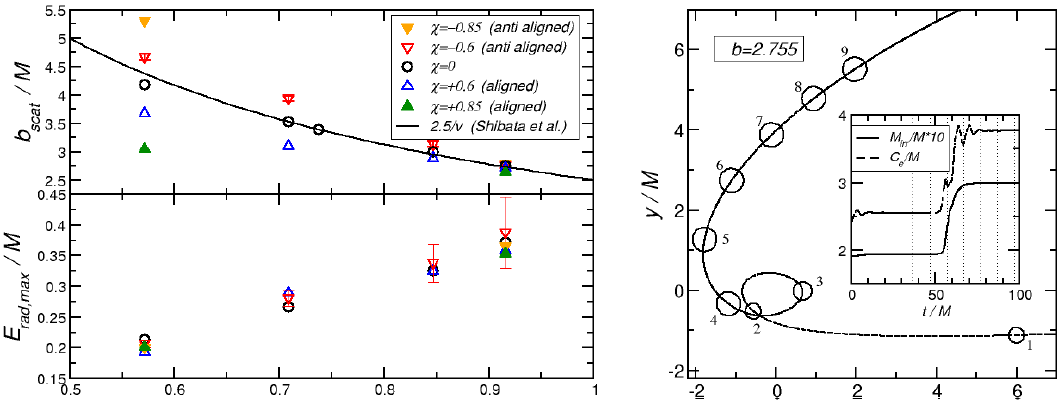
Figure 15: Left panels: Scattering threshold (upper panel) and maximum radiated energy (lower
panel) as a function of  . Colored “triangle” symbols pointing up and down refer to the
aligned and antialigned cases, respectively. Black “circle” symbols represent the thresholds for the
nonspinning configurations. Right panel: Trajectory of one BH for a delayed merger configuration
with anti-aligned spins
  . The circles represent the BH location at equidistant intervals
 corresponding to the vertical lines in the inset that shows the equatorial circumference
of the BH’s AH as a function of time.
 . Colored “triangle” symbols pointing up and down refer to the
aligned and antialigned cases, respectively. Black “circle” symbols represent the thresholds for the
nonspinning configurations. Right panel: Trajectory of one BH for a delayed merger configuration
with anti-aligned spins
  . The circles represent the BH location at equidistant intervals
 corresponding to the vertical lines in the inset that shows the equatorial circumference
of the BH’s AH as a function of time.